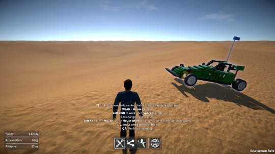
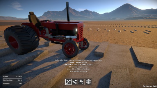
GearBlocks Demo 0.5.6628

GearBlocks Demo 0.5.6628

Part 1 of a series of videos demoing some of the fantastic GearBlocks community builds from last year.  I meant to do this at the end of the year, but I was working on adding a third person camera to the game and I wanted to wait until that was in, as it better shows off these creations!

Parts 2 and 3 will be coming soon…

GearBlocks Demo 0.4.6450

GearBlocks Demo 0.4.6450

Slopes and wedges

Here’s what I’ve been up to over the last couple of weeks.  I’m still working on the company set up stuff, it’s unfamiliar territory for me, so I had to do a bit of research and get advice from some people.  I won’t bore you with the details, but it seems there’s no getting around the complexities that require both an accountant and lawyer.  This is going to cost me a lot of money, so I want to be sure before going ahead with it!

Upcoming demo

I’ll upload the demo update as soon as the company is sorted (should be soon now), but in the meantime, here’s a sneak peak at the changes that will be in it:-

  • Improved builder tool controls and usability:-
    • Changed alignment and attachment indicators for improved visibility and clarity.
    • Improved part selection (restricting selection location to where part can be attached).
    • Better selection rotation behaviour during alignment.
    • Improved part resizing response to key presses.
    • Added part resizing indicator to show available resize directions.
    • During alignment attachment indicators are now shown for any attachments that will be created.
    • Selected construction can now be frozen in place during alignment.
  •  More user configurability:-
    • Configurable key bindings for the various actions in the game.
    • Replaced single graphics “quality level” setting with individual settings for more fine grained control.
    • Added many other options (such as mouse look sensitivity and invert, camera FOV, etc.)
    • Improved sound options (volume controls and speaker configuration).
  • UI improvements:-
    • Improved screen layouts and UI elements.
    • UI is now scaled based on screen resolution.
    • New part and attachment info UI overlays.
    • New game stats UI overlay.
    • Improved in-game context sensitive hints.
  • Updated and improved parts:-
    • Improved part behaviour key binding.
    • Differential gears now have limited slip behaviour, with tweakable “slip limit strength”.
    • Lights can now (optionally) have a key bound to switch them on and off, just like motors.
    • Beams now resizable down to 1 unit in length, and plates from 1×1 to 25×25 units in area.
    • Better wheel friction behaviour.
    • Increased max spring rate and damping values for spring dampers.
    • All part models (except wheels) now textured.
    • New light parts (now with paintable lenses).
    • New seat models (replacing old ones).
    • Wheel rims now paintable.
  • Rendering changes:-
    • Construction materialise / dematerialise effect.
    • Part paint application fade in / out.
    • Corrected part paint colour (de-gamma’d, it now visually matches colour shown in UI).
    • Upgraded time-of-day system.
  • The construction frozen state is now saved / restored from saved games.
  • New and improved sound effects (toolbox, footsteps, ambient loop).
  • Minor tweaks to desert proving ground map.
  • Bug fixes.

As usual I’ve updated any parts that were already in the demo, but I’m not adding any additional ones, all the new parts I’m making are for the full game only!

Slopes and wedges

image

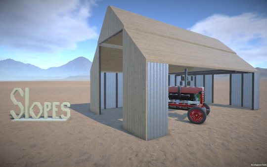
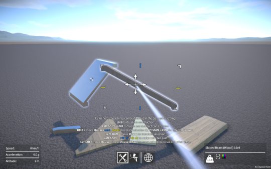
On the subject of new parts, I’ve now implemented resizable sloped beams and plates, as well as resizable wedge plates.

image

Designing their shapes was a bit of a challenge because I had to find a compromise between these three competing requirements:-

  1. Be easily representable by box colliders for efficient physics.
  2. Have plenty of room for attachment points.
  3. Look good when combined with other slopes, plates, etc.

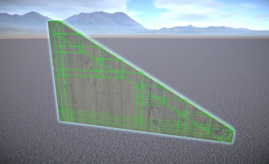
The wedge shape was the trickiest to represent with box colliders.  I contemplated using a convex mesh collider for it, but I wanted to avoid this as they are generally less efficient for physics, and I also have part intersection tests in the game that only work for primitive colliders.  So instead I created a system to dynamically add box colliders, three for the wedge edges, and then recursively adding more to fill in the wedge interior (the larger the wedge, the more interior colliders are needed).  An example of this can be seen below.

image

All resizable parts in GearBlocks use procedurally generated meshes, so I had to implement mesh generation for these new slope and wedge parts.  This wasn’t too difficult but did require a fair bit of refactoring of my procedural mesh system to allow for these more intricate shapes.

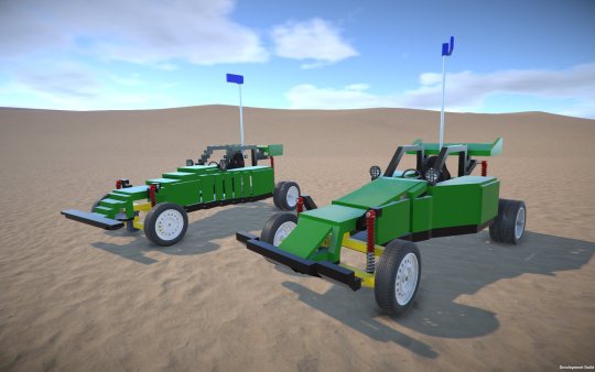
Here’s a comparison of the Desert Buggy construction, the original version vs. one I made using the new slope and wedge parts.

image

Not only does the slopes and wedges version look way better, it uses nearly 50 fewer parts than the original!

In the future I want to add a compound sloped plate (i.e. a “corner” piece), as well as curved beams and plates.  The trouble is, the colliders for these will be even more tricky to set up.  I might need so many box colliders to represent these shapes that it wouldn’t be practical, so I may well have to resort to convex mesh colliders for these.  Anyway, something I’ll come back to later.

Construction interface problems

The sloped plate part is the first part in the game that is resizable along all three axes.  Unfortunately this particularly highlights the awkwardness of the current part positioning and resizing interface.  I’m not sure what I’m going to do about this yet, but I think I’ll have to revisit the construction controls yet again.  There has to be a way I can make this better, but I’m just not seeing it right now!

So where is that demo update already?

So, um, that demo release I’ve been promising, where is it you might ask?  The good news is, it’s ready to release (has been for a while actually).  The last thing was to set up an installer for it and that’s all done now (if you’re wondering, I used Inno Setup for this, found it a super easy tool to use, with great results!)

Unfortunately, I can’t release it just yet as I’m still working on getting my company set up.  This is turning out to be more complicated and expensive than I first realised.  Incorporating the company itself is easy, but because I’ve already been developing GearBlocks for a while, I’ll need to transfer GearBlocks IP to the company, which complicates things and adds to the cost (accountant fees on top of the lawyer fees!)  Anyway, I’ll keep plugging away at this and hopefully get it done in the next week or two.

In the meantime I’ve been adding more parts – some new sliding rack gears with integrated ball joints / hinges (makes for neater steering systems), more lights, and a seat.  I’ve also implemented limited slip functionality in the differential gear, with configurable “locking strength”, should keep that wheel spin under control!

I plan on adding various types of sloped / curved beams and plates to the game, this will make constructions look a lot better (and save on the number of parts needed in a lot of cases).  Next week I’ll start work on what should be the simplest of these, a resizable sloped beam.

Wheel physics revisited

Last week I decided to take another look at the wheel physics implementation, in particular the tire friction model.  First let’s quickly recap how the wheel physics works in GearBlocks.

Wheel physics recap

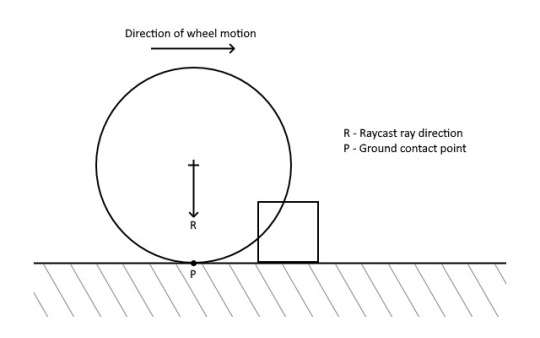
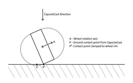
Every update I find the contact point on the ground directly below the wheel and position a configurable joint there.  This joint is then connected to the wheel at the closest point on its outer edge to the contact point on the ground.  The joint has a linear limit set up to prevent the wheel going below the ground, which provides the wheel to ground collision response.

For friction between the tire and ground, I set up the configurable joint’s velocity drive to constrain the wheel’s velocity at the contact point to zero, with the maximum force on the drive being set to the friction force.  To calculate the friction force, I use a method inspired by the Coulomb damping model, where the friction force equals the product of a friction coefficient and the normal force at the contact point (i.e the force preventing the wheel from sinking into the ground).

Previous tire friction hack

To find the normal force I need to know what force the configurable joint’s linear limit is applying to keep the wheel above the ground.  However, it used to be that in Unity there was no way to access this (even though it was available in PhysX), so I had to estimate the normal force by taking the total mass of the construction, dividing it by the number of wheels, and multiplying it by the acceleration due to gravity.  Basically a total hack, because it assumed the vehicle’s weight was always distributed exactly evenly over each wheel.

Improved tire friction

Well the good news is it turns out that fairly recently the joint force was made available in Unity (via Joint.currentForce), so I’ve now switched the implementation over to use this to find a proper normal force.  This means that in a vehicle, weight distribution now affects tire grip, and because the normal force is now being calculated dynamically, weight transfer also affects grip in the way you’d expect, which is pretty cool.  This all sounds great, and is a definite step in the right direction, but there’s a problem.

Formula magic

By using Coulomb damping I’m effectively assuming that tires are rigid (i.e. non-elastic) which of course they’re not.  In reality a tire’s grip changes depending on how much it is sliding across the ground (tires actually develop peak grip when sliding slightly).  Not only that, the longitudinal (forward and back) and lateral (side to side) grip of a tire behaves slightly differently.  So most driving simulations instead use some form of “friction curves”, equations that you plug slip amounts into and get friction forces out.  The industry standard is the Pacejka tire models, sometimes known as “magic formulas”, these are empirical models that have been made to fit real world measured data, the equations themselves don’t have any basis in real physics as far as I can tell.

Sounds simple enough, so why not use the magic formulas?  Well, after looking into this for a bit, I can see several problems:-

  1. The equations for the Pacejka curves themselves are complicated and have a ton of tuning parameters, something I’d prefer not to have to deal with.  Probably overkill for what I need anyway.
  2. The slip values used to lookup into the curves are actually slip ratios.  The upshot being that at low velocities numerical instability becomes an issue (and at zero velocity you’ve got a divide by zero – the slip ratio is undefined!)
  3. Because you need to evaluate longitudinal and lateral slip separately, there’s the question of how to combine the resulting separate friction forces.  You can’t just add them together because a tire can only develop so much grip at any one time, the more longitudinal grip you “use up”, the less lateral grip is available, and vice versa.  This effect is sometimes known as the tire’s “traction circle”.

I’m sure there are ways around all of these problems.  The Pacejka equations could be substituted with something simpler for example, and I’ve seen various ideas out there that attempt to properly combine longitudinal and lateral slip.  The slip ratio numerical instability issue I’m less sure about at the moment, apparently a lot of driving sims switch to another simpler friction model at low velocities to get around it, seems a bit hacky though.

Another related issue is that I’m not even differentiating friction levels between different surfaces (e.g. tarmac vs. dirt) yet, so perhaps a realistic tire friction model isn’t worth it at this point?  Anyway, something to keep thinking about and revisit again in the future.

Construction controls (again), and props

Selection points

Over the last few weeks I’ve been working on fixing something with the construction controls that’s been bugging me for ages.  I wasn’t happy with the range of positions at which you could select a part, you could select it anywhere within its bounds, which wasn’t really restrictive enough.

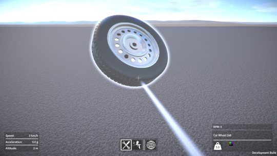
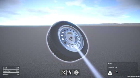
Here’s an example.  You could select anywhere on a wheel, even though it only has one point that can attach to anything.

image

Much better to restrict the selection point to always be at this attachment point as shown below, that way it feels more natural when attaching the wheel to another part.

image

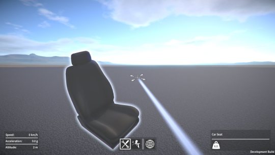
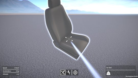
This next example is even worse.  You could select anywhere on a seat, and then translate it so that the selection point was completely outside the seat which is just plain stupid.

image

So now I restrict the selection point to be somewhere in the region on the bottom of the seat where its attachment points are, so you always have it selected in a suitable place ready to attach to another part.

image

To accomplish this I had to rework some code so that it now automatically calculates the selection region based on where all the part’s attachment points are located.  The upside to this was that I could do away with explicitly specifying the allowed translation directions on each part.  The less I have to manually setup per part the better!

I also had to implement some new math functions to find the closest point on the part’s selection region to the player’s eye “ray”.  Took a while to do, but it’s never a bad thing to add more stuff to my math toolkit I suppose, could come in handy for other things in the future.

All this took way longer than I expected, it was only supposed to be a couple of day’s work, sigh.

Prop parts

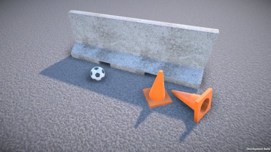
I’ve also added some new “prop” parts.  Props are a new category of part that are the simplest objects in the game, they don’t have a behaviour and they don’t attach to any other part.  The idea is that they can be used with the machines and vehicles you build or placed in the world to set up a scene to play in.  For example, traffic barriers could be laid out to form a race track, the ball could be used in a Rube Goldberg machine.

image

As with all the other parts, I’ll be adding more props as I go, any suggestions for these are welcome!